Next: Inserting the PCA Results Up: Down-hole Seismic Processing Previous: Post genvsp processing steps Contents Index
The geometry will be complete once the down-hole tool horizontal component
orientation has been established as described in Michaels (12).
We begin by running the genbhod program which builds scripts
that control the hodogram analysis by program bhod. The following
is the dialog between genbhod and the user (boxed). The program is run
from inside the directory with the newly created L*.seg files (created from
Bison format):
 |---------------------------------|
 | Copyright (C) 2017  P. Michaels |
 |       All rights reserved       |
 |see GNU General Public License   |
 |---------------------------------|

 WARNING: !!
 See Source Code, genbhod.f, or BSU documentation
 (man pages and BSU user Guide)
 before you use this program. It is hardwired for
 a specific type of acquisition.

 enter 1char_ALPHA PREFIX
L
  enter FIRST FILE NUMBER (<=3digits)
  for which source polarization is 270 deg.
2
  enter LAST FILE NUMBER (<=3digits)
  for which source polarization is 270 deg.
146
  enter UP/DOWN SWITCH
    -1= 90 Azimuth File Number 1 LESS than 270 Az
    +1= 90 Azimuth File Number 1 MORE than 270 Az
-1
enter azimuth of bowspring(R-comp)
240
  OUTPUT====> Downhole: gobhodo
  OUTPUT====> Reference: gobhodoR
  OUTPUT====> Downhole: gorunbhod
  OUTPUT====> Reference: gorunbhodR
  ----------------------------------------
 REMEMBER to change permissions on the
 above files to execute.
  ----------------------------------------
  IF examining the Down-hole Phone

  1. Run gobhodo in directory with 6 chan
  records (3 down, 3 reference phones)

  2. Run gorunbhod in directory with files
  that are named hxxxyyy.seg

  ----------------------------------------
  IF examining the Reference Phone

  1. Run gobhodoR in the directory with
  the 6 channel records.

  2. Run gorunbhodR in the directory with
  files that are named rxxxyyy.seg

  ----------------------------------------
Because the tool is fixed for both source polarizations, there will be half as many orientation determinations as there are seismic files. The tips at the bottom of the dialog are reminders about which scripts are for what purpose. In a normal case, one generally is only interested in the down-hole tool orientation, and will only run scripts gobhodo and gorunbhod. If you are interested in viewing the actual rotation of the radiation from the source with time, then you will run the other two scripts, gobhodoR and gorunbhodR (the upper case ``R'' being a reminder that these are for the fixed reference phone). The following steps are recommended:
mkdir hodo
will do this nicely.
mv h*.seg hodo
rm bscl*
cp gorunbhod hodo
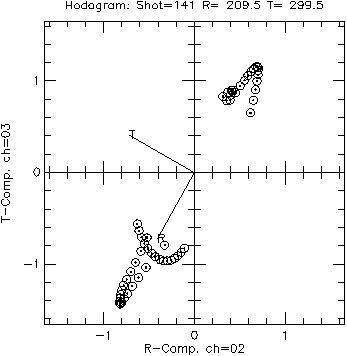
Since this is a shallow station, it corresponds to the observed orientation
of the bow spring when the tool exited the hole. Without the guide
vector (set at ![]() in the dialog above), the resulting R-component
direction could easily have been rotated by
in the dialog above), the resulting R-component
direction could easily have been rotated by ![]() due to the
inherent ambiguity in the eigenvector solution. The line in the file
bhod.lst corresponding to this station is: 00141
209.5 299.5 from which you can see the meaning of the 3 columns.
The first column corresponds to the file number, the second column
the R-component azimuth, and the third column is the T-component azimuth.
The values will be truncated to integers when written to the headers
by program btor.
due to the
inherent ambiguity in the eigenvector solution. The line in the file
bhod.lst corresponding to this station is: 00141
209.5 299.5 from which you can see the meaning of the 3 columns.
The first column corresponds to the file number, the second column
the R-component azimuth, and the third column is the T-component azimuth.
The values will be truncated to integers when written to the headers
by program btor.
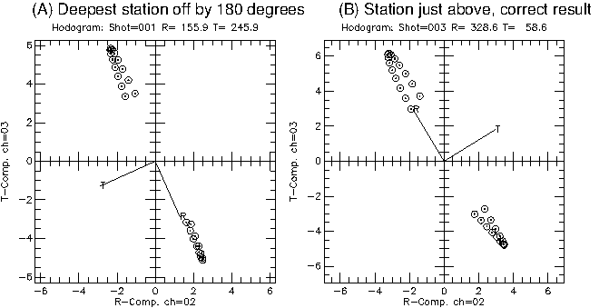
There is one case in which bhod returned a tool orientation
rotated by ![]() . This is for the deepest level. The tool twisted
enough during the survey to make the single guide vector insufficient.
With only one problem, it is easier to edit the bhod file directly.
. This is for the deepest level. The tool twisted
enough during the survey to make the single guide vector insufficient.
With only one problem, it is easier to edit the bhod file directly.
Figure 13 shows the problem with the deepest level. In the figure are two hodograms, one for h001.seg, and the other for h003.seg (the next shallower station). You will see from examining file merge.pdf that h003.seg and shallower levels resulted in a consistent set of tool orientations.
The way to correct the deepest level here is to change the line in the bhod.lst file. The current first few lines are:
00001 155.9 245.9 <--this one is in error
by ![]()
00003 328.6 58.6
00005 323.1 53.1
00007 314.1 44.1
The first line should be manually edited so that these lines become:
00001 335.9 65.9 <--fixed, rotated by
![]()
00003 328.6 58.6
00005 323.1 53.1
00007 314.1 44.1
The result is a consistent set of orientations, and one that continues to the surface and agrees with the observed orientation of the tool as it exited the hole.